

Main Rotor Drive System
The main gear box translates the engine power to the main rotor system. It does this by a series of reduction gears which takes the high rpm's of the main drive shaft and reduces it via a planetary gear set to the low rpm's needed by the rotor system. This reduction in shaft speed greatly increases the available torque and a lower main rotor speed also allows for higher forward airspeed as retreating blade stall is delayed.
However in a two bladed high inertia system, higher main rotor speeds are needed versus a 3, 4, or 5 bladed system and this in turn helps to explain the relatively slower airspeed of the 206 versus a comparable helicopter such as the AS350 or MD500. However high inertia rotor systems have a unique safety advantage in that they offer better performance in auto rotation, just in case the engine fails in flight.
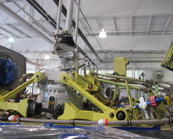
Here you can see how the flight controls from the servos reach the main rotor blades. Notice how the bell cranks are mounted on the main gearbox and not directly to the swash plate. This allows the in and out motion of the servos to change the angle of the swash plate by pulling or pushing on any of the two non-rotating swash plate arms and collective lever. The action on the swash plate moves it in relation to pilot input on the cyclic and collective levers into an angle. When the rotating portion of the swash plate moves, it is guided by the non-rotating portion and this movement changes the angle of the main rotor blades through the use of the main rotor pitch control rods.